

技術(shù)文章 / Technical articles
There are a lot of contact angle meters or contact angle measurement instruments with different measuring method or made by different manufactory. And, quality and working accuracy of these contact angle meters or contact angle measurements instrument is quite differ from each other. How to choice most suitable contact angle meter for us is more important. This article will show you how to begin your contact angle measuring experience by choosing the most suitable contact angle meter from different manufactory in worldwide.
Material which you want to measure is always taken seriously when one choose contact angle meter. Actually, material such as fiber (especially measuring contact angle between resin and single fiber, or single fiber with super-hydrophobic surface), powder (with contact angle above 80゜) and uneven surface is difficult to measure contact angle. All of these need special ways to measure contact angle. (Email us to get more information about measurement of contact angle for these conditions)
Material with Super-Hydrophilic (contact angle below 3゜) surface (such asaluminum foil of air conditioning) or super-hydrophobic (contact angle above 140゜) surface (such as lotus leaf or water strider leg) is also difficult to measure contact angle. General method of contact angle meter is useless in this condition.
So, when you measure such material as described above, you should tell it to you supplier and ask them for a suitable solution.
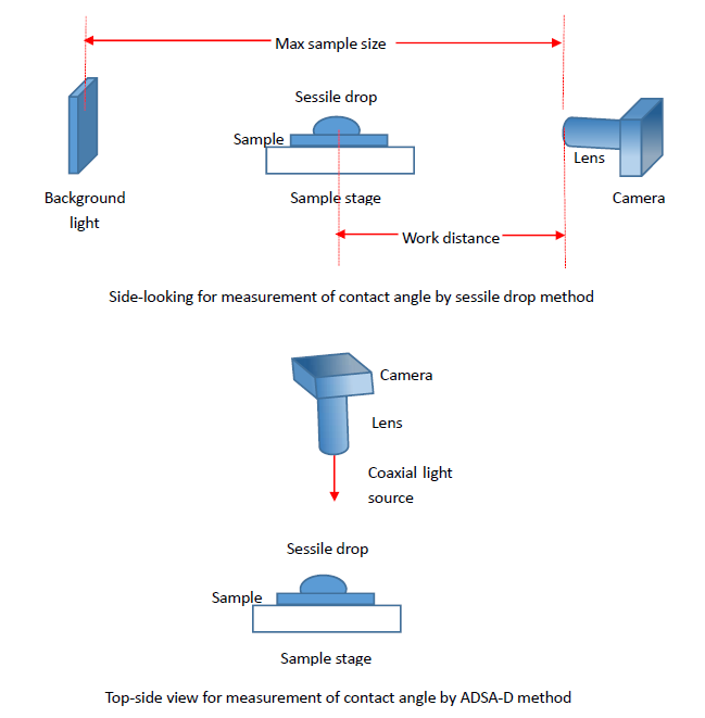
The second thing we should consider is outline dimensions of measuring sample, especially size of one side and thickness of sample, because to capture small droplet image, work distance of lens is usually not very long (max. word distance of lens with 0.20X auxiliary lens is about 360mm). And in commercial contact angle meter, work distance of lens is usually about 170mm and it can used to measure contact angle for sample with size of one side about 300mm. As an alternative when we measure contact angle for especially large sample such as LED displayer, we use prism to refract the observation angle and background light. (Refer portable contact angle meter model SL200P series).
The third thing that need to be considered is concave sample. Due to view of lens is side-looking, contact angle of concave sample cannot be measured using normal sessile drop method. We should use top-side view to measure contact angle of such sample and use ADSA-D method to calculate contact angle.
There are about ten methods to measure contact angle (refer: surface science techniques, Gianangelo Bracco Bodil Holst editors, springer 2013, ISBN 978-3-642-34243-1, for more information), including the following methods:
This is usually called as contact angle goniometer. The most widely used technique of contact angle measurement is a direct measurement of the tangent angle at the three-phase contact point on a sessile drop profile. The first commercial contact angle goniometer is designed by W.A.Zisman, and was manufactured by Ramehart instrument company. Usually, contact angle meter with camera but without complexity algorithm (such as drop shape analysis system) is also called as contact angle goniometer. Most manufactory’s contact angle measurement instrument is fall into this category except contact angle measurement instrument with drop shape analytical system. Refer 2.10 drop shape analysis system for more information.
Instead of forming a sessile drop on the surface of solid, an air bubble is formed beneath the solid sample, which is immersed in the testing liquid. This method is very useful for material with Super-Hydrophilic (contact angle below 3゜) surface (such as aluminum foil of air conditioning) or super-hydrophobic (contact angle above 140゜) surface (such as lotus leaf or water strider leg).
2.4Wilhelmy balance method:
The Wilhelmy balance method is a widely used technique that indirectly measures contact angle on a solid sample. The Wilhelmy balance technique is an indirect force method. It is usually used to measure dynamic contact angle of smooth and known wetting length. And sometimes, it is maybe an alternative solution when one want to check sessile drop method. Some manufactory that don't make optical method will always emphasize advantage of this method and ignore its disadvantage. So, we must be sure what we really want, then you will make a good choice.
It has several advantages over conventional optical methods. First, the task of measuring an angle is reduced to the measurements of weight and length, which can be performed with high accuracy and without subjectivity. Second, the measured force at any given depth of immersion is already an average value. Although this feature does not help determine the heterogeneity, it does automatically give a more accurate contact angle value that reflects the property of the entire sample. In addition, the graph produced by this technique (Fig. 1.8) is useful for studying dynamic contact angles and contact angle hysteresis at different wetting speeds. The smoothness of the curve indicates the heterogeneity of the solid sample. It is even possible to study absorption or surface reorientation by repeating the submersion circle. However, the method also suffers from several drawbacks. The solid sample must be produced with a uniform cross section in the submersion direction. Rods, plates, and fibers with known perimeters are ideal samples, but it is sometimes difficult to measure the perimeter and the wetted length precisely. Other than regular geometries, the sample must have the same composition and topography at all sides, which might be difficult to meet, particularly if one wants to investigate films or anisotropic systems. Also, a sufficient quantity of liquid must be used, which might cause the solid sample to swell and/or absorb vapor unintentionally.
2.5Capillary rise as a vertical plate:
When a liquid comes contact with a vertical and infinitely wide plate, it will rise due to the capillary effect. The height of capillary rise h can be determined by the integration of the Laplace equation
sin θ = 1 − Δρgh2/(2γlv).
This method is rarely used in commercial contact angle meter or any other contact angle measurement instrument.
2.6Individual or single fiber:
The above mentioned Wilhelmy balance method is probably the most reliable technique for measuring contact angles on individual fibers of known diameter. The precise value of the fiber diameter can be determined by using a liquid of known surface tension to wet the fiber completely (i.e., zero contact angle). Given that cos θ = 1, the perimeter p of the fiber can be calculated from whilhelmy balance equation. Similar to the solid plate used in Wilhelmy balance method, a continuous immersion circle of the fiber in the liquid can also be used to test the homogeneity of the fiber surface.
But, for fiber with diameter about 5um, we usually used micro-balance with precise 0.001mg (1ug). It is more expensive.
Sometime, this solution may be out of work due to liquid for test is viscosity or fiber is variable bended.
2.7Capillary tube:
In circumstances when both the inside and outside surfaces of the capillary tube are made of the exact same material, the Wilhelmy balance method can be used to measure the contact angle. The perimeter p of the capillary tube should be the sum of the inner and outer perimeters. In general, the Wilhelmy balance method can be applied to a wide range of plates, rods, wires, tubes, and capillaries.
2.8Capillary penetration method for powders and granules (Modified and extended Washburn method):
The capillary penetration method was developed by Washburn, who monitored the rate at which a liquid penetrates into a compressed powder cake. The measurement was achieved by recording the depth of the liquid front intrusion as a function of time. The contact angle can then be deduced according to Washburn theory:
l2 = rtγlv cos θ/2η
where l is the depth of liquid intrusion, γlv is the liquid surface tension, θ is the contact angle, η is the liquid viscosity, t is the time required for penetration, and r represents the pore radius. Numerous qualitative measurements have been performed, and the method has been developed theoretically .
But this method need to find a liquid that can form contact angle about 0゜on powder, and when measuring contact angle is above 90゜, this method is useless.
There are about 5 methods for measuring contact angle of powder. Email us for more information.
2.9Caplillary bridge method:
Restagno et al. developed a high-precision contact angle measuring technique, which they referred to as the “capillary bridge method”. In their experiment, a spherical solid surface (usually a watch glass) is put in contact with a large liquid bath. Due to the capillary effect, a meniscus or “capillary bridge” forms around the contact line, which defines the wetted area on the solid surface. The shape of this “capillary bridge” between the solid surface and the liquid changes as the solid is slowly moved up or down to give a systematically varying wetted area. By monitoring the changes of the wetted area and the distance that solid surface moves, the dynamic contact angles can be quantitatively determined through numerical resolution of the Young-Laplace equation or by a simplified approximated relation:
A = 2πR(k −1(2(1+cos θ)) ^(1/2)−h)
2.10Drop shape analysis system:
Bashforth and Adams were the first to use the Laplace equation to analyze the shape of droplet profile. They manually generated a collection of sessile drop profile according to different values of surface tension and the radius of curvature at the drop apex. Consequently, the task of determining surface tension become simple interpolation from their tables. Their tremendous contribution led to booming development in the area. Blaisdell, as well as Tawde and Parvatikar extended the Bashforth and Adams tables. Fordham and Mills generated equivalent tables for pendant drops. Ever since digital computers become popular, drop shape analysis has been greatly improved, and many new methods have been developed.
Usually there are 3 generation of drop shape analysis system. Most manufactory’s contact angle meter used Young-Laplace equation fitting method based on selected plane method (such as Kruss, Dataphysics, KSV, Ramehart, etc.)
Refer http://www.uskino.com/article/64.html for more information of drop shape analysis system.
Generally, contact angle meter (contact angle goniometer) is always consist of (1) Sample stage and its control system, (2) Dosing system and its control system, (3) Vision system and its control system, (4) Environment chamber, (5) Drop shape analysis software. So, choose contact angle meter for your purpose based on its functional module maybe a most useful way. And, you can also check out the rationality of contact angle meter’s function designs.
(1) Sample stage and its control system:
- Size of your sample will affect your choosing of travel range of XY direction if you want to measure all point located on sample surface.
- Which control system do you want? Manual control system or automatic control system that controlled by software?
- The weight of the sample. Some contact angle measurement equipment adopts rack and pinion dovetail stage, and its load capability is poor.
- Do you need rotating system for measurement of dynamic contact angle or thermodynamics intrinsic contact angle? Contact angle meter model SL200K and C60 are equipped this system as standard accessories.
(2) Dosing system and its control system
- Direct syringe pump or Multi-syringe pump? Later is for measuring surface free energy, and we use different liquid to measure contact angle in this case. But, later is contaminated easily due to difficult for you to cleantube.
- Manual or automatic syringe pump. First one is cheaper and its dosing precision is also possible down to 0.02uL (with 100uL syringe pump).
-Manual or automatic transferring the drop to sample surface.
-If it has mechanical system corresponding to adjustment focus distance and position of needle?
(3) Vision system and its control system
- What speed of camera do you want? If you measure sample with super absorbent, you should choose high speed camera such as 100FPS or higher.
- The reliability and accuracy of measurement of contact angle or surface tension. If the budget allows, you can choose vision system with telecentric lens and parallel light background light to achieve higher accuracy of measurement contact angle or surface tension.
(4) Environment chamber:
- What temperature do you want?
- Do you carry out measurement of contact angle or surface tension under condition of pressure or vacuum?
- Do you need humidity environment?
(5) Drop shape analysis software
- What function do you want?
- Measurement of static contact angle or dynamic contact angle?
- Do you want to measure surface tension or interfacial tension by drop shape analysis software using pendant drop or sessile drop method?
- Do you want to calculate surface free energy?
- Do you want to measure dynamic surface tension or interfacial tension?
Note:
1, 2, 3 Control of sample stage along XY axis is used for measuring contact angle of different position on sample surface. And, control of sample stage along Z axis is used for measuring sample with different thickness. KINO is only manufactory of contact angle meter that adopts motorized linear stage or manual positioner for motion control system. By comparison, contact angle meter made by other factory always uses common adjustment mechanism such as “dovetail stage” or just one optical bench with holder unit and height adjustable rod stand. (Note: these is always used for quick and long travel range adjustment that need no accuracy.)
For more information of them, visit https://www.newport.com/Products/5465115/1033/nav.aspx orhttp://www.sigma-koki.com. KINO’s contact angle meter adopts such motion control system as this manufactory’s and accords with its design accuracy. You can find difference such as load capacity and travel accuracy between rack and pinion dovetail stage, translating optical post holder and crossed-roller guide positioner with micrometer. It is shown that crossed-roller guide positioner with micrometer is most suitable for vertical position. Motorized linear stage controlled by software with slide guide provide more stable and smooth movement and positioning of drop.
4, Level adjustment of sample stage except adjusting complete machine by four adjustable legs is most important. For example, after you adjusted levelness of sample stage at first, when you measure sample with poor level surface, it is more difficult to get good base line and obtain two contact points. As shown below:
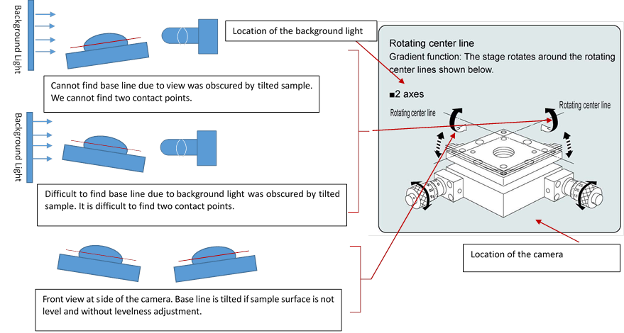
Tilting system for measurement of roll-off angle of KINO’s contact angle meter adopts motorized rotation stage with very low backlash, low wobble (about 40urad) and high absolute accuracy (about 0.01°) . KINO exclusively provides you specially designed mechanical Structure (Rotating only Lens, sample stage and its control system) instead of rotating complete machine. Accuracy and backlash of latter is very poor due to control complete machine is very difficultly.
6, We suggest our customer to choose direct single syringe pump instead of syringe pump with tee-junction because latter is difficult to clean and easily lead to cross contamination e.g. water for measurement of contact angle is contaminated by oil.
|
|
|
|
direct single syringe pump - Advantage: Easy to clean and remove syringe, High precision, pollution-free. - Shortcoming: inconvenient to measure contact angle with multiple liquid. |
syringe pump with 3 port value - Advantage: Difficult to clean pump, value and tube, easily lead to cross contamination, cannot dosing liquid with viscosity - Shortcoming: convenient to measure contact angle with multiple liquid when equipped with multi-channel pump. |
7, usually, there are two drop transferring method- by move needle down and then up or by move sample stage upside and downside. We prefer first method due to we can easily control the base line of contact angle (it remains at same position) by first one. By second one, base line is bound to move because sample surface moved during this process. And for measuring contact angle of super-hydrophobic surface, movement of needle must be very carefully because it is difficult to transfer drop to this surface. So, we adopt positioner stage with micrometer or controlled by step motor to get high precision of control.
8, Interface of Camera that USA KINO adopted is USB2.0 or USB3.0, which is more mutually compatible with PC than IEEE1394a or IEEE1394b. Most suitable resolution of camera for contact angle meter is about 130M, and 40M is most common resolution that used. Visit http://www.uskino.com/news/50.html to find more information about this topic.
9, Telecentric Lens and Parallel light Background light are most suitable for contact angle measurement for the following reasons. With them, we can benefit highest precision measurement values at sub-pixel resolution.
(1) Magnification Constancy
Common lenses give different magnifications at different conjugates: as such, when the object is displaced, the size of its image changes almost proportionally with the object-to-lens distance. This is something anybody can easily experience in everyday life, for example when taking pictures with a camera equipped with a standard photographic lens.
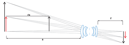
With telecentric lenses the image size is left unchanged with object displacement, provided the objectstays within a certain range often referred to as “depth of field” or “telecentric range”. This is due to the particular path of the rays within the optical system: only ray cones whose barycentric ray (or “principal ray”) is parallel to the opto-mechanical main axis are collected by the objective. For this reason, the front lens diameter must be at least as large as the object field diagonal. This optical behaviour is obtained by positioning the stop aperture exactly on the focal plane of the front optical group: the incoming rays aim at the entrance pupil which appears as being virtually placed at the infinity. The name “telecentric” derives from the words “tele” (which means “far” in ancient Greek) and “centre” which accounts for the pupil aperture, the actual centre of an optical system.
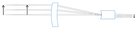
Fig. 2: in a telecentric system rays get into the optics only with an almost parallel-to-the-axis path.
(2) Low Distortion
Distortion is one of the worst problems limiting measurement accuracy: even the best performing optics are affected by some grade of distortion, while often even a single pixel of difference between the real image and the expected image could be critical.
Distortion is simply defined as the percentage difference between the distance of an image point from the image center and the same distance as it would be measured in a distortion-free image; it can be thought of as a deviation between the imaged and the real dimensions of an object. For instance, if a point of an image is 198 pixels distant from the center, while a distance of 200 pixels would be expected in absence of distortion, the radial distortion, at that point, would be
Distortion = (198-200)/200 = -2/200 = 1%
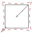
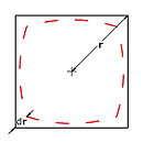
Fig.3: “pincushion” type distortion “barrel” type distortion
Positive radial distortion is also called “pincushion” distortion, negative radial distortion is called “barrel” distortion: note that the distortion depends on the radial position and can also change of sign. Distortion can be also viewed as a 2D geometrical transformation of the real world into the virtual space created by the lens; as this transformation is not perfectly linear but is approaching 2nd or 3rd degree polynomials, the image becomes slightly stretched and deformed.
Common optics show distortion values ranging from some percent to some tens percent, making precise measurement really difficult; things get even worse when non-telecentric lenses are used. Since most machine vision optics have originally been developed for video-surveillance or photography applications, relevant distortion values have usually been considered acceptable, as the human eye can compensate distortion errors up to 1-2%. In some cases, like in fish-eye lenses or webcam-style lenses, distortion is intentionally introduced to make the lens work on large angles also providing an even illumination of the detector (in these cases distortion is helpful in reducing cosine-to-the-fourth law effects).
High quality telecentric lenses normally show a very low distortion degree, in the range of 0,1%; although this amount seems to be very small it would actually result into measurement errors approaching the size of one pixel of an high resolution camera. For this reason, in most applications, distortion has to be software calibrated: a precise pattern (whose geometrical accuracy must be at least ten times better than the needed measurement accuracy) is placed at the center of the field depth; distortion is then computed at several image points and, based on these data, the software algorithm transforms the native image into a distortion-free image. Few people know that the distortion also depends upon the distance of the object, not only upon the optics itself; for this reason it is very important
Few people know that the distortion also depends upon the distance of the object, not only upon the optics itself; for this reason it is very important that the nominal working distance is strictly respected.
A fine perpendicular alignment between the lens and the inspected object is recommended in order to avoid non-axially symmetric distortion effects. Trapezoidal distortion (also known as “keystone” or “thin prism” effect) is another important parameter to be minimized in an optical inspection system as it is asymmetric and very difficult to software calibrate. Lens focusing mechanism can also introduce some symmetric or non-symmetric distortion effect because of mechanical play or optical element decentering.
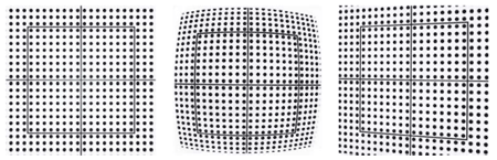
Fig. 4: on the left an image of a distortion pattern taken with a telecentric lens, where no radial or trapezoidal distortion is present. In the middle the image of the same pattern showing strong radial distortion. On the right an example of trapezoidal distortion.
(3) Perspective Errors limitation
When using common optics to image 3D objects (non completely flat objects) far objects will look smaller than close objects. As a consequence, when objects like a cylindrical cavity are imaged, the top and the bottom crown edges will appear to be concentric although the two circles are perfectly identical.
On the contrary, by means of a telecentric lens, the bottom crown edge will disappear because the two crown edges are perfectly overlapping.
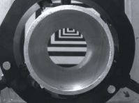
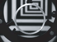
Fig. 5: Common optics showing significant image perspective error (on the left). A telecentric lens is able to cancel any perspective effect (on the right).
One could describe a common lens as a mathematical function building a correspondence between the 3-dimensional object space and the 2-dimensional detector (image) space while a telecentric would build a 2D-2D correspondance as would not display an object’s third dimension thus making it the perfect component for profile imaging and measurement.
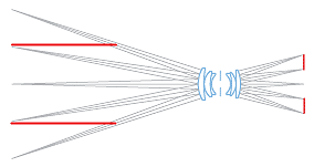
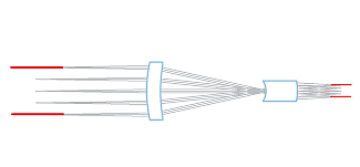
Fig. 6: Common optics (left) project longitudinal geometrical information onto the detector, while telecentric lenses are not.
(4) Good image resolution
Image resolution is decribed by CTF (contrast transfer function) which quantifies the contrast ratio at a given spatial frequency on the camera detector plane, expressed in lp/mm (line pairs per millimeter).
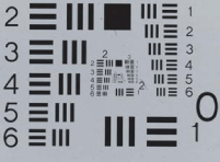
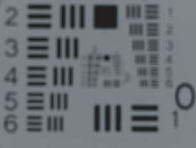
Fig. 7: good and bad contrast achieved with optics of varying CTF looking at a standard USAF test pattern.
Quite often, machine vision integrators tend to combine cameras having tons of small pixels with cheap, poor resolution lenses, resulting in blurred images; the resolution provided by telecentric lenses is compatible with very small pixel sizes and high resolution cameras thus increasing the measurement resolution.
(5) No edge position uncertainty
When common back lighting an object it can often be difficult to determine the exact position of its edges.
This can happen because the bright pixels in the background tend to overlap with the dark pixels at the object edges. Moreover, if the object is highly 3D-shaped, also a border effect could furtherly limit the measurement precision; as shown in the following drawing, rays grazing the object edges at certain incidence angles could be reflected by the surface, but still be collected by the lens.
The lens would then see those rays as if they were coming from behind the object; as a result, slices of the image could disappear, thus making the measurement very much imprecise and unstable.
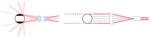
Fig. 8: Border effects in a common imaging lens are strongly reduced by means of a telecentric lens
This effect can be efficiently limited by means of a telecentric lens: if the pupil aperture is small enough, the only reflected rays which could enter the lens would be those nearly parallel to the optical main axis.
As these rays are affected by very small deflection, the reflection from the object surface doesn’t jeopardize the measurement accuracy.
To get rid of such issues, Parallel light Background light (also called “collimated” or “telecentric”) illuminators can be interfaced to telecentric lenses, taking care of matching the lens aperture and FOV with the collimated source divergence. With this option, all the light coming out of the illuminator is collected by the lens and delivered onto the detector, allowing extremely high signal-to-noise ratios and incredibly low exposure times. On the other hand, only “expected” rays come into the imaging lens so that no problems occur at the borders.
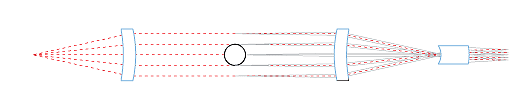
Fig. 9: Parallel light Background light (Collimated light, telecentric) illumination projects only the expected rays into the imaging system.
We captured some images use using 2 different combinations of lens and background (one is common lens and diffused background light as used in general contact angle measurement instrument, another is used telecentric lens and Parallel light Background light)
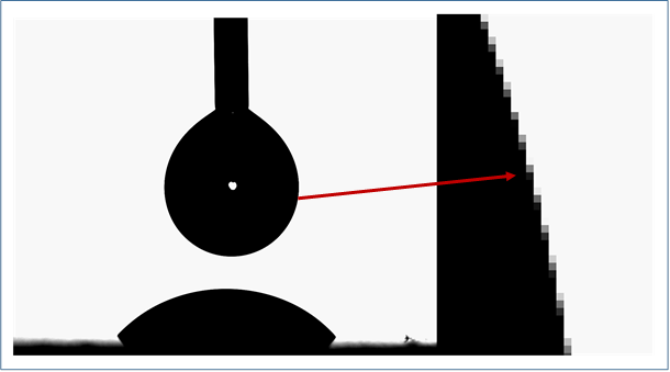
Fig. 10: Image of pendant drop used Parallel light Background light and telecentric lens. We can find little change range of sharpness at image edge when zooming it about 1500X.
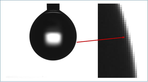
Fig. 11: Image of pendant drop used common Background light and lens. We can find more change range of sharpness at image edge when zooming it about 1500X.
Fig. 12: Image of sessile drop with little change range of sharpness used Parallel light Background light and telecentric lens.
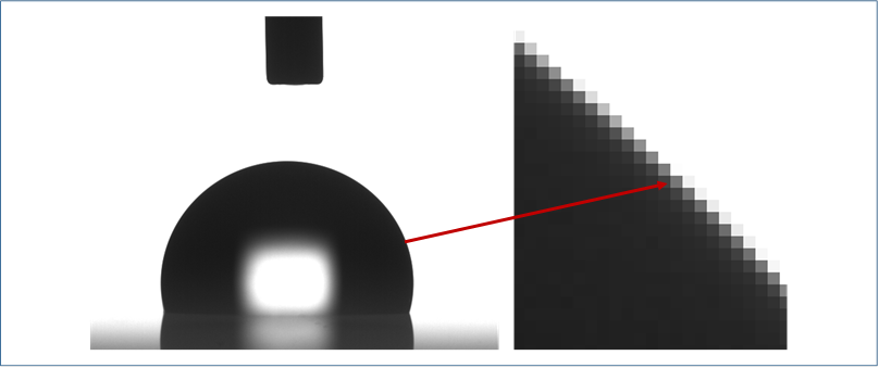
Fig. 13: Image of sessile drop with more change range of sharpness used common Background light and lens.
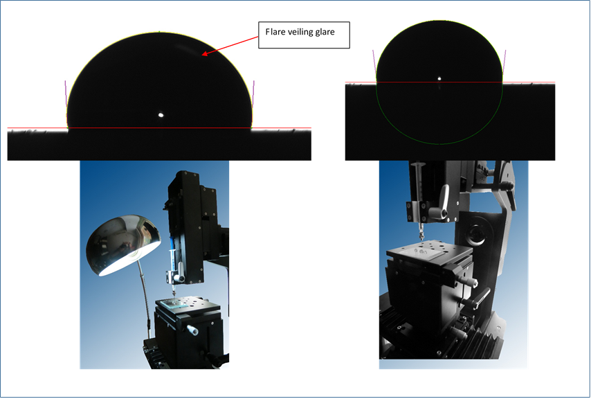
(5) Not disturbed by flare veiling glare
Flare veiling glare will not disturb image capture process.